› Forums › Spectroscopy › LHires experience – and some issues…
- This topic has 44 replies, 6 voices, and was last updated 5 years, 8 months ago by
 Mr Jack Martin.
-
AuthorPosts
-
5 August 2018 at 11:52 am #574100
 Kevin GurneyParticipant
I have been commissioning my new LhiresIII and, while I think I have some reasonable spectra, I have encountered some problems along the way, and would appreciate comments on how I have tried to overcome them. Apologies for the long post but I thought I would keep it together rather than fragemnt over several…
(i) Distortion (coma) in the guide image. This is pretty severe and threatened to make reliable placement of a star on the slit quite hard. I found, however, that there was a ‘sweet spot’, horizontally around 20-25% of the way from one edge of the image, and about 10% down form the mid-line. This means the image of my slit is quite far over to the right. The problem seems robust to changes in guide cam focus and guide mirror adjustment (lateral movement). Even ayt this location the star images are not perfect but they are workable. I wonder if anyone else has seen this? Is it an issue taht is exacerbated by the use of a Ritchey Chretian scope (GSO style 10in)?
(ii) Vertically wide spectrum image. I found this confusing at first… My spectrum image extended vertically over about 80 pixels or so and, over this range, there were vertical gradations in the intensity. I then recalled something in the instructions about setting the main miror to be offset so that ‘vignetting’ was avoided. I didnt understand what this meant (vignetting for me is a 2D gradation in a ‘pretty picture’ image rather than the pseudo-1D of a spectrum image) but it dawned on me that it could refer to my problem. I therefore set about moving the mirror over the small angular adjustment afforded by the oval cutout around the clamp screw on the base (It helps to loosen the other, pivot-end, screw as well – not in the instructions, but trial and error… :). This allowed me to have a narrow spectrum image with no gradation and I have now settled on this. The spectrum is not in the centre of the sensor, but I dont think this is critical… (?). What I think a vertically narrow image buys you is good calibration (?).
(iii) Calibration at bluer end of the spectrum. If you step too far outside the comfort zone of Ha, then calibration can get tricky because the Neon lamp lines become sparser and weaker. I think I have managed to overcome this with extended exposure during calibration (30-60s) and I am very grateful to Robin’s mapping of the neon spectrum on his web page – it’s an invaluable reference! However, it strikes me that an auxiliary Argon lamp may help , but my internet search only showed lab equipment at around £400 – is there anything more mundane out there?
(iv) Ritchey Chretien/spectroscopy combo. (Here’s one for Andy…:). My Altair Astro RC is great for general imaging (beautifully flat fields etc, with little coma). However, the large central obstruction gives a bigger Airy pattern, with more energy in the surrounding rings than in the central disc (the ‘soft focus’ issue in imaging with RCs – there is no free lunch!). My star images overlap the slit extensively (I am using motorised focus with numerical analysis of the disc image, so I think its as good as it gets…) – but should I worry? In the Lhires exposure calculator spreadsheet availble online, the central obstruction factor doesn’t make as much diference as I thought – so maybe not? I have also experimented with the optional 35mu slit. Its early days on this one, but this doesn’t seem to give the 50% (35/23) improvement in signal I was expecting.. ? I know it downgrades resolution but at R =12000, I think you get most of what you want to see?
Phew! Many thanks to those who read to the end – I look forward to your comments.
Kevin
5 August 2018 at 5:17 pm #579811 Andy WilsonKeymaster
Hi Kevin,
I will reply to your points ii and iv, and perhaps a bit on i, as I think they may be related. I have the same setup as you, an LHIRES III and a GSO 10″ RC.
When I first started with my LHIRES III, I concentrated on trying to get perfect guide stars and a perfectly narrow spectrum. I was getting some very nice results. Then after a few months I tried tweaking things to get the maximum throughput. I found I was getting my best results by going for a compromise setup. By that I mean that the spectrum is not perfectly narrow, and neither is the guide image perfect. It is possibly I gave up too early, but from conversations with Shelyak and other users, I think the sweet spot is genuinely a compromise setup.
My main learning was not to concentrate on getting the narrowest possible spectrum. I realised this when I started using MaximDL to examine spectra on the fly. Not looking to maximise the counts in the centre of the spectrum, or trying to get the narrowest possible spectrum, but instead to get the largest combined counts across the height of the spectrum. Hopefully you understand what I mean, which is basically you want as many photons to pass through the slit and spectrograph, reaching the detector. I found this might not be when the star appears perfectly focused on the slit, or the spectrum image as narrow as possible. This seemed a bit crazy at the time, and maybe I am still missing something, but I kind of assume it is something to do with the slit being a half-silvered glass plate. It is worth noting I don’t mean a horrible guide image or spectrum, just not absolutely perfect.
Here are a couple of images to try to illustrate what I mean. First an image of the spectrum of gamma Peg at high spectral resolution.
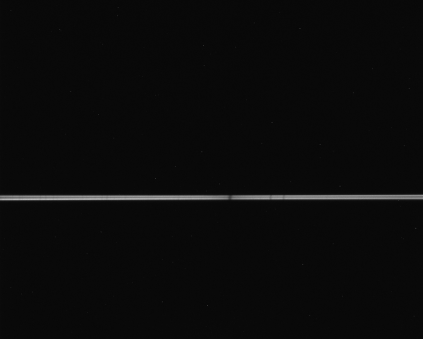
You can see the image is not perfectly focused as the central obstruction shows in the middle. However, if I examine the vertical profile using a box area in MaximDL I see the following.
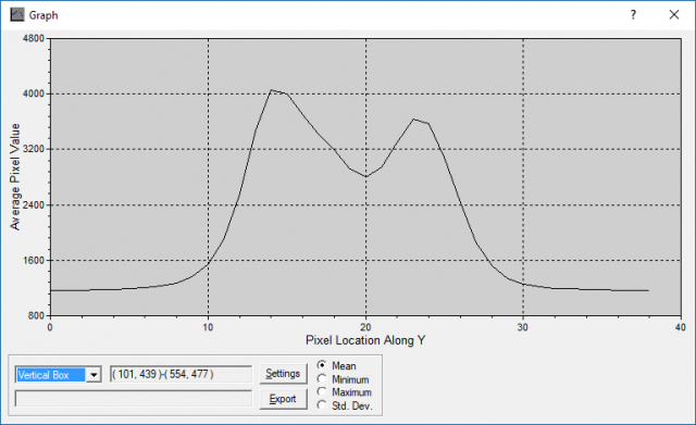
So the dark centre is far from being black, but contains a lot of signal. I tried various ways to improve the look of the spectrum, to make it look more ‘Gaussian’ in cross-section and I did achieve this. However, when I did thorough checking of the results, I was always getting less photons.
So when I focus, I aim to maximise the cross-sectional area of the spectrum, not the star on the slit. Just to be clear these are small changes, so the stars still look reasonable in the guide camera. To use this method of focusing (this is focusing the telescope), you need a star that is bright enough to give a decent spectrum in 10-20 seconds but not so bright that the spectrum starts to saturate. With shorter exposures you will be chasing seeing affects rather than true focus, and longer exposures will take a long time to try out different focus positions to reach the sweet spot.
I find there is very little image shift in the GSO 10″ RC unless the temperature really varies a lot during the night. So I can spend a decent time getting good focus, and then often leave it for weeks.
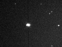
With regard to the guide image, here is an example from my setup for comparison.
I hope some of this helps. It would be interesting to hear if other LHIRES III users found similar results to me, or get their best results with the narrowest spectrum.
Cheers,
Andy
5 August 2018 at 5:58 pm #579812 Robin LeadbeaterParticipant
Hi Kevin,
I have seen all these issues with the LHIRES and hopefully can help work through them. Firstly can you confirm it is the latest model (ie it is a new LHIRES, not just new to you ?)
Cheers
Robin
5 August 2018 at 7:02 pm #579814Robin LeadbeaterParticipantIf you look into the spectrograph with the imaging camera removed, you can see the diagonal mirror which sends the light towards the grating through the lens. It is important that the return beam misses this mirror when it returns to the camera. This is achieved by rotating the mirror. The mirror should be adjusted so the spectrum is approximately 1/3 the way up from the bottom of the camera field when the spectrum is horizontal and orientated with red on the right.
The fact that the focus of the spectrum (The width of the spectrum line) is varying so much as you adjust the mirror. (80 pixels means the spectrum is way our of focus). I do not recall seeing this before This suggests to me something may be out of alignment. We may have to revisit this.
Cheers
Robin
5 August 2018 at 7:10 pm #579815Robin LeadbeaterParticipantIf you have the latest design, Shelyak supply an alternative calibration lamp which can be used in place of the neon which includes Ar and other elements.(The same as used in the ALPY and LISA)
https://www.shelyak.com/produit/se0148-argon-neon-spare-bulbs/?lang=en
It has the disadvantage that there are lots of lines which can be difficult to identify so I suggest sticking to the neon and H alpha initially while we get the spectrograph up and running.
Cheers
Robin
5 August 2018 at 7:26 pm #579816Robin LeadbeaterParticipantFor a circular star image, the amount of light passing through does not increase proportionally to the slit width so the penalty is not as large as expected. Having said that,I would expect your scope optics to be seeing limited on axis so for good throughput I would aim for a slit width equivalent to around 3 arcsec for typical uk seeing. (I use a 35um slit with my C11 at f10). Is your scope f8? in that case 23um might be better for you and give higher resolution. You will get a bit of vignetting in the spectrograph at f8 though which will lose you a bit of light compared with my setup at f10. (The spectrograph optics are f8 but you have to allow extra for the angle between the undispersed and dispersed beams so an f8 beam will not quite fit through the optics)
Robin
5 August 2018 at 8:33 pm #579817Kevin GurneyParticipantHi Andy
Thanks for full response…
Yes, your image of the spectrum looks like those I was getting before I adjusted the main mirror (i.e. a bimodal profile). I take your point about it being integrated flux rather than some peak value that is important. I will go back and have a look at that.
Your main guide star looks pretty round to me (albeit with the left hand side lobe which appears ubiquitous in these gude images). I’ll try and take some later if possible to compare. The idea of scope focusing using spectral throughput as the measure is also interesting (But I woud have thought that a correctly adjusted guide-assembly would imply otimal throughput?)
cheers
Kevin
5 August 2018 at 8:48 pm #579818Kevin GurneyParticipantHi Robin
Thanks for series of tips..!
First, yes, it is a genuinely new one (so includes all latest bells and whistles)
You will see I noted to Andy that the kind of spectrum I was getting was similar to the one he posted (bimodal cross section) so I’m not sure about the focus thing? I focus the collimator (terminology? i.e. the assembly behind the small door on the side) against the FWHM of the calibration lines.
The bimodal feature appears to come and go as I move the main mirror about its fulcrum. However, I see you recommend placing it about 1/3 way *up* (with red on right). I have it about 1/3 way *down* so maybe I’ll try swinging across the field of view (and taking some cross-sectional integrated flux measurements as I do so).
Many thanks
Kevin
5 August 2018 at 8:51 pm #579819Kevin GurneyParticipantHi Robin
You are certainly right that messing with additional lamps isn’t going to help me with a basic setup! But I couldnt resist ‘looking to see’ some of the other curiosities in the spectrum…
Kevin
5 August 2018 at 8:55 pm #579820Kevin GurneyParticipantMy scope is indeed f8 but seeing here isnt brilliant, what with the urban heat dissipating etc…
Can you explain what you mean by ‘vignetting’ here? Do you mean the star disc spreads beyong the slit? For the stars I am looking at this is certainly the case. In this respect (star diameter vs slit width) my guide images look liek the one Andy posted above.
Kevin
5 August 2018 at 9:00 pm #579821Robin LeadbeaterParticipantHi Kevin,
OK as you have the latest version, you get the updated optics which should have improved the off axis coma. (I have not really used my LHIRES since I installed the upgrades but am just reinstalling it on the scope so should be able to report back in the next few days. The new design has removed most of the adjustment degrees of freedom of the guiding mirror (you can just push it in and out) so you are dependent on it being aligned correctly at the factory (with the old system you had full adjustability but was tricky to get spot on. I have kept the old adjustment system on mine) The sweet spot with round stars should line up with the slit but in this case being so far from the centre suggests an alignment problem somewhere. In the back of my mind I remember a similar comment from someone ese. You could check your guide camera is concentric with the guide port and square but beyond that I would be tempted to bounce that back to Francois at Shelyak and ask him to comment.
Cheers
Robin
5 August 2018 at 9:11 pm #579822Robin LeadbeaterParticipantHere I am talking about the light beam after the slit. It has to fit through the collimator in both directions. The collimator is f8 but there is an angle between the beam in each direction and the return beam is also dispersed by the grating so is wider. This means an f8 beam will overspill the collimator hence the f10 design specification for the LHIRES. Running at f8 does not affect the spectrum quality appreciably though, you just lose a bit of light. In spectrograph design there is a trade off between slit width, focal ratio and resolution. The upshot is though for a given resolution, the size of spectrograph optics scales with telescope aperture.
Robin
5 August 2018 at 9:31 pm #579823Robin LeadbeaterParticipantHere is a post on spectro-l from Francois Cochard back in 2010 which helped me when setting up my guider.
https://groups.yahoo.com/neo/groups/spectro-l/conversations/messages/7119
and here is my comment in the same thread on the sweet spot position
https://groups.yahoo.com/neo/groups/spectro-l/conversations/messages/7079
Robin
5 August 2018 at 11:27 pm #579824Robin LeadbeaterParticipantSo it does ! I need to recheck this then. (I was shown how to set it up this way at OHP workshop back in 2006.) The photos in the manual are rather confusing as they appear to show the spectra running vertically, displaced to the left. It also looks like the manual (on line at least) is well overdue for an update as it still shows the original kit built instrument with the adjustable slit and the old guider and calibration lamp setup.
Cheers
Robin
6 August 2018 at 12:05 am #579825Robin LeadbeaterParticipant>Do you mean the star disc spreads beyong the slit? For the stars I am looking at this is certainly the case. In this respect (star >diameter vs slit width) my guide images look liek the one Andy posted above.
Images of the star on the slit can be deceiving if the star is over exposed as the overspill looks worse than it is. Best to measure the typical FWHM of the point spread function of the star when correctly exposed and in focus. Matching the slit width to this is a good compromise as most of the light will pass through the slit and you will optimise the resolution. With your setup 23um corresponds to 2.4 arcsec and 35um is 3.6 arcsec. I would not go any wider as you lose too much resolution. You cannot reduce the star size using a focal reducer either as that produces more vignetting in the spectrograph. When you do these sorts of calculations you begin to see how the telescope, local seeing and spectrograph design are intimately linked. The LHIRES is optimised for an 8 inch f10 with 2.5arcsec seeing.
Robin
EDIT: Found the calculator I was looking for. For a gaussian shaped star profile, 76% of the light will pass through a FWHM wide slit.
https://spectroscopy.wordpress.com/2009/05/22/slitpinhole-flux-calculator/
6 August 2018 at 11:13 pm #579826Kevin GurneyParticipantHi Robin
Many thanks for lead…
I looked at the yahoo group posts and spent the afternoon getting to grips with Francois instructions… I could see that, in my current configuration, the slit didn’t apper central in the image of the guide scope aperture; it was way off…
However, to correct it, I had to tilt the whole mirror assembly forward slightly which was effected using a washer on the top screw. I set up earlier but its clouded out here now so, unfortunately, I will have to wait for a proper field test.
On the matter of the position of the main mirror: I carried out several experiments last night and hope to get back with proper analysis later…But preliminary thought are that the best throughput (total flux) appears to be with the spectrum in the lower half (as you suggested) but it does increase the height of the image. However I think this might not matter – some careful examination of results required.
In any case, having explored the construction of the ‘business end’ more carefully, I have a better understanding of the light path. I think perhaps they should make you assemble them after all!
cheers
Kevin
7 August 2018 at 11:35 am #579828Robin LeadbeaterParticipantYes mine was one of the original kit versions. Having to assemble it from a box of bits taught me a lot about how it works. You can still see the assembly photos and drawings on Olivier Thizy’s website
http://astrosurf.com/thizy/lhires3/index-en.html
I have asked for confirmation about the main mirror adjustment on the ARAS forum.
>it does increase the height of the image. However I think this might not matter
The large change in width of the spectrum with the mirror position is strange. I am pretty sure I do not see this but I need a clear sky to check and the run of good weather has broken at this end of the country.
A wide spectrum, even if it does not affect the total flux is not ideal as you have to sum more rows, introducing more noise from the camera and sky background.
If the spectrum is wide when the star is focused on the slit (ie the flux is maximum), this can be due to astigmatism. ie the focus of the collimator lens in the dispersion direction (as set up by making the lamp lines sharp) is different to that in the vertical direction. (The spectrograph design has some inherent distortion of the image but this is small) . I had this issue once when I overtightened the grating in the holder, distorting it slightly into effectively a cylindrical lens. I am note sure how the gratings are supported in the latest design. A possible test for this could be to check the zero order image of a star without the slit in place. In this configuration the grating is effectively a mirror so the image should be round. I have not tried this though.
When the grating was not pinched I did not see any significant difference in focus between the guider and the spectrum image. (ie when the star was in focus on the slit the spectrum was narrow.) This is true for both my ALPY and LHIRES.
Cheers
Robin
7 August 2018 at 11:55 am #579829Robin LeadbeaterParticipant>A possible test for this could be to check the zero order image of a star without the slit in place. In this configuration the grating is effectively a mirror so the image should be round. I have not tried this though.
Actually, checking back I see I did run this test. (though only after I had cured the astigmatism.) The test report is attached.
Cheers
Robin
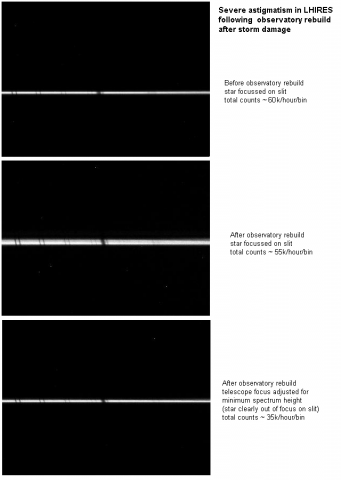
7 August 2018 at 12:22 pm #579830Robin LeadbeaterParticipantAttached are examples of before and after spectra when the grating was overtightened after a rebuild, though unfortunately I did not do the zero order test before I cured it which would have conclusively proved astigmatism. With the spectrum at its narrowest, the star was out of focus on the slit and the throughput was low. Adjusting the telescope so the star was in focus on the slit gave good throughput but a wide spectrum. Once the grating clamps were slackened off. Everything returned to normal (The star was in focus on the slit, the spectrum was narrow and the throughput was good)
Robin
 8 August 2018 at 10:25 am #579832Kevin GurneyParticipant
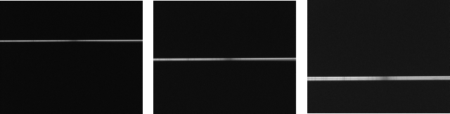
I have now experimented with the main mirror adjustment, see below…
[For some reason my original 640×163 image has become vertically squashed, but I think you get the idea…]. Red is to the right.
Anyway – the important things are:
(i) The spectrum gets wider (more height in Y-axis) as it goes down the sensor.
(ii) As well as this, the overall integrated flux gets bigger – an increase of around 50% from the two extremes explored here. I am assuming the final Isis image has removed the background and so the flux is signal, rather than background+signal. (You might expect total flux to increase just because its a bigger area…)
(iii) However, the spectrum is not so good in the larger-flux, lower-in-image version. In particular, it doest work well with the optimal binning option; there is a strong reduction of blue end amplitude. You can recover the blue end by unchecking ‘optimal binning’ (in ISIS) but – a) I don’t think this is good practice (optimal means… optimal I guess?). b) there is some loss of resolution (narrow atmospheric lines are not quite as deep).Assuming some steady progression of behaviour from the version on the left (spectrum in top half) to that on the right, I think I will be aiming for something like the left hand image on my jpg below… Here its about 1/3 way down.
Kevin
-
AuthorPosts
- You must be logged in to reply to this topic.